|
|
Post by Mr. Metallic on Feb 14, 2022 8:08:04 GMT -5
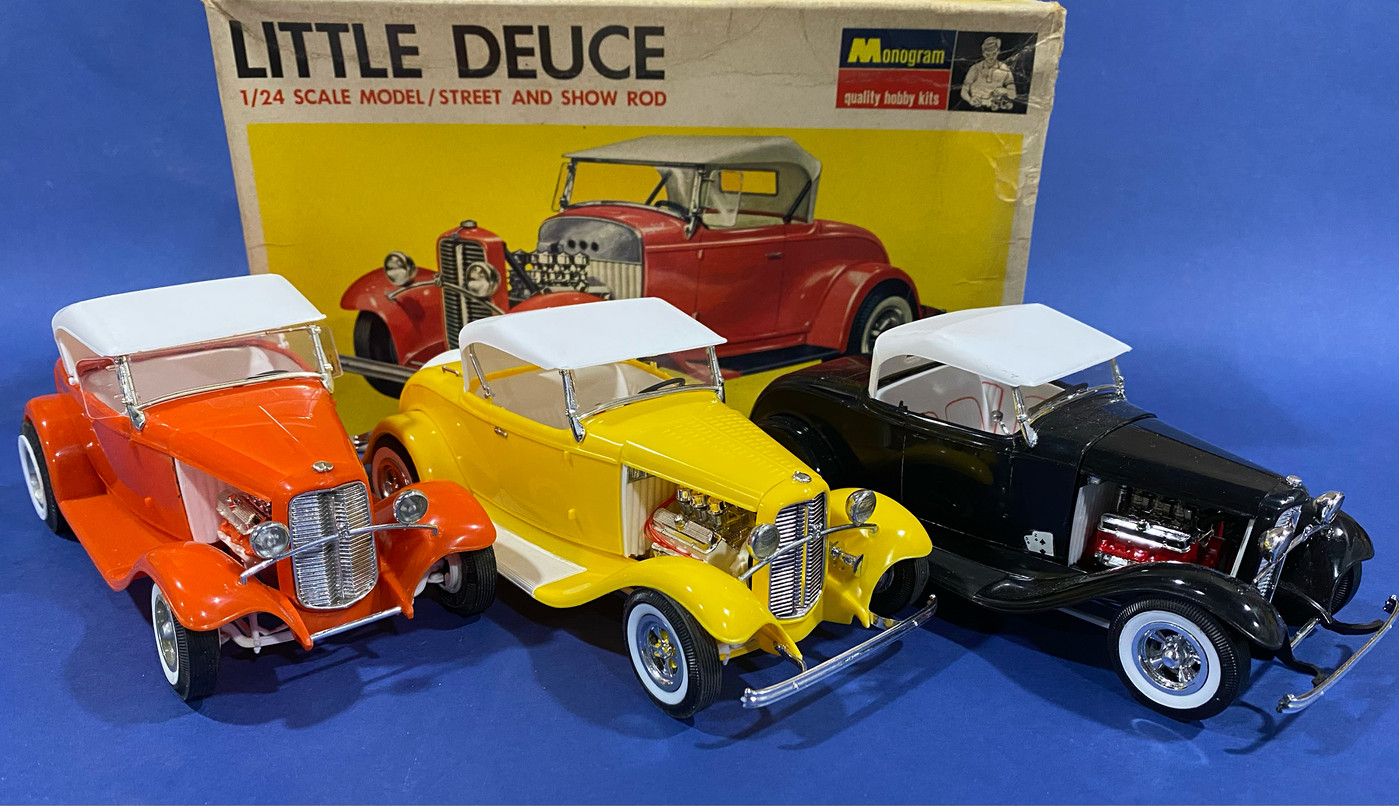
Simple... that's the intention. How many of us start out a project and say to ourselves "going to try to keep this simple"? Well, that's the intent with the project. The bench time I did get last year was mostly dedicated to my series on Monogram hot rods and some restorations. I've loved those, and they've been great to get the creative juices flowing again. But that's the problem, the ever lengthening backlog of project ideas in the old (slowly failing) memory bank. The intent with this project was to get one of those long lingering ideas on the bench, and to get it executed as simply as possible. Enter the Revell 30 A. I want to get something very close to the style and design of the car below, using minimal but purposeful kitbashing/aftermarket parts to show how to turn the new Revell 29 roadster/30 coupe kits into something a little more "traditional". I will try to emulate the project style of one of my favorite influencers of this hobby Mr. Tim Boyd in showing just a few tweaks one can make to a kit to make it something they can call their own. I'll be using the first version of the coupe with the Chevy small block, but most of the ideas and techniques I apply to this build can be used on any of the now 4 versions of this kit series to have been released over the last 6 years (after an agonizingly long break in the middle of those 6 years with no kit on the shelf). I performed most of these modification over about 8 hours at a Build n' Bull I hosted over the weekend. I'll break the different stages of the build into multiple posts so it's a little easier to digest. Here is the inspiration for this project. Yes, it's 32 (and channeled), but the stance and flavor is the inspiration here. 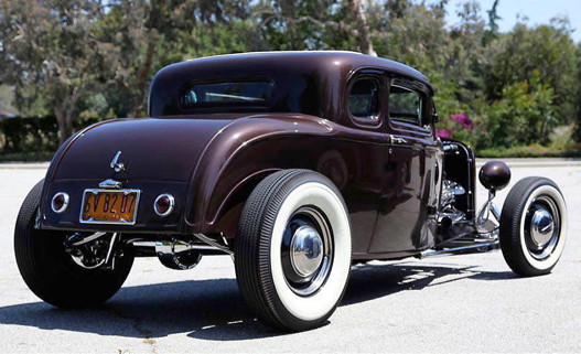 |
|
|
|
Post by Mr. Metallic on Feb 14, 2022 9:19:38 GMT -5
The Frame: I have built a few of these Revell model A's already, so I knew where to start. The way the frame was engineered the crossmember, while great for positively location the floor pan (and by extension the interior/body) is also a curse because it holds all of it about 1-2 scale inches above the frame itself. I'm not using that tubular trans crossmember on my build, so that helps. The rear crossmember that accepts the shocks/springs also does the same, but that will get removed as well for this traditional styled build. But don't remove that one yet, you need it to positively locate the floor to the frame for awhile while you perform the next modification. Even after that rear crossmember would be removed you'd note the ribbing on the underside continues to hold the floor away from the frame. Begin by taping the floor to the frame, and marking where the ribs run under the frame (note red marks). Remove the tape and then carefully remove the ribbing that would be under the frame so the floor can sit flush on the frame. 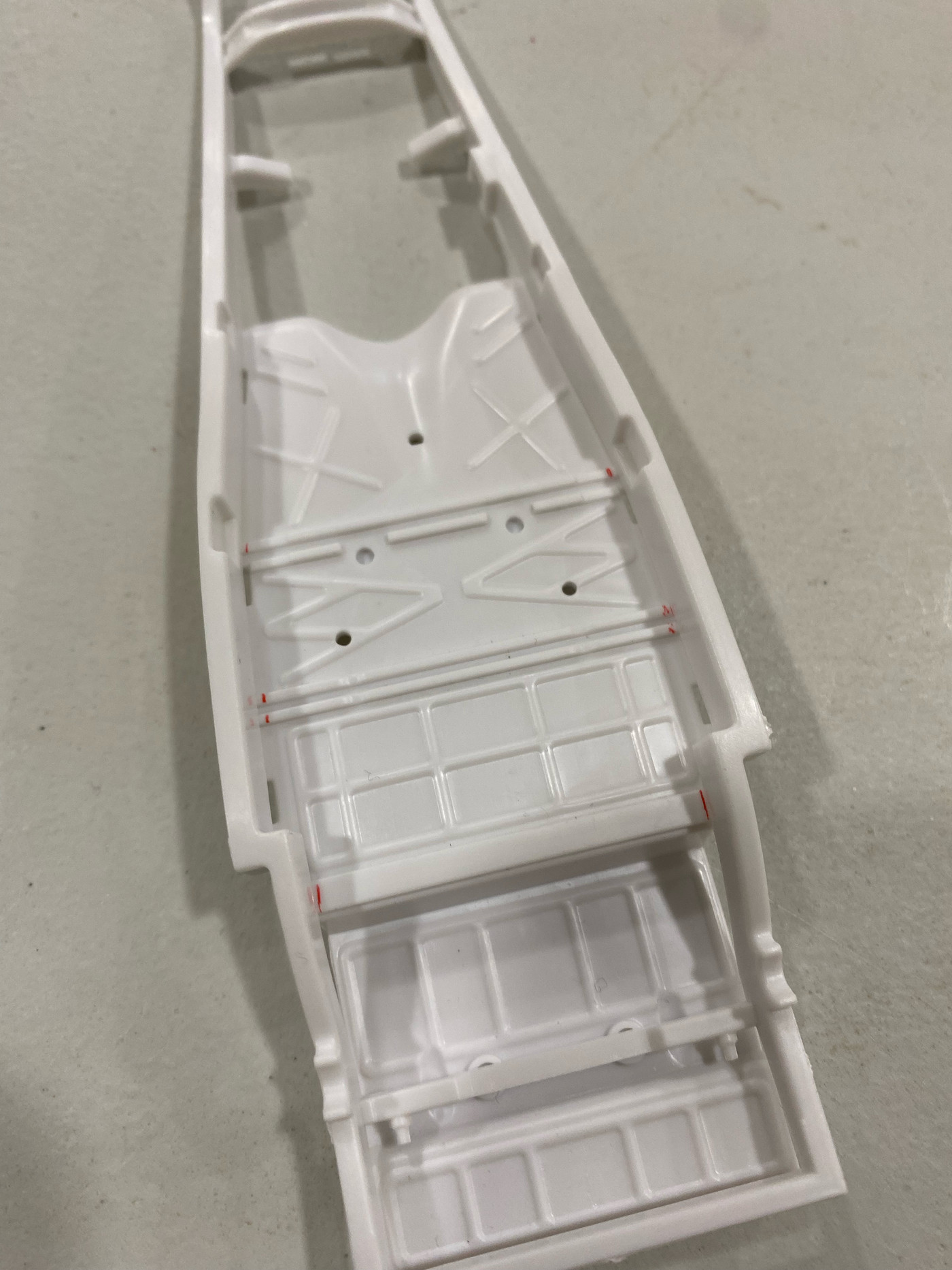 Next is the rear crossmember. For a 40's to early 60's hot rod the kit supplied coil spring setup has got to go. You can use whatever buggy sprung style Ford rear or even a quick change rear end if that's your preference. I'll be using the stock Ford rear from a Monogram 30 Woody simply because I had one readily available, but there are lots of other choices out there and the installation process would be very similar. I removed the crossmember from the 30 woody frame with a couple quick snips and then set about to clean up the mold lines (and paint, this was rescued from a builtup) and set it aside. Now you can go ahead and remove the molded in rear spring/shock crossmember. To determine where the new crossmember would sit on the frame you have to get the spring/axle temporarily assembled. The way this setup comes in the kit the spring sits in a notch on top of the axle. That orientation tends to leave the stance a bit high for my taste, so I relocated the spring to mount behind the axle. I use pins for a lot of my assemblies because it provides a strong mounting point and allows for repeated assembly/disassembly for mockups. So I drilled a hole on the bracket on each end of the spring and glued a pin in the hole. After the glue dries trim the pin to length. What I typically do to locate my corresponding hole on the mating part is touch the end of the pin with a marker and then press the parts together, leaving a dot of ink where the mating hole needs to be. Drill your holes in the axle and mock up your new rear end assembly. 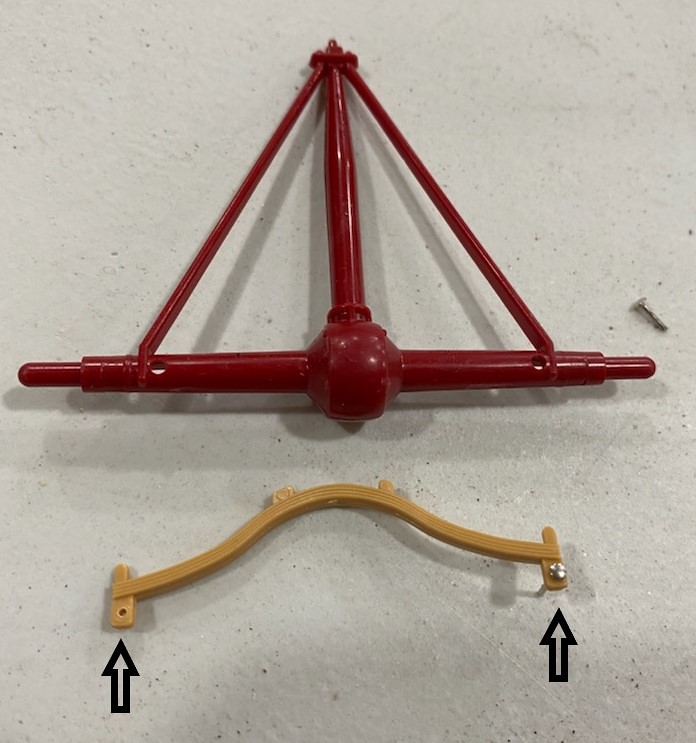 Now you can determine where the crossmember needs to go. What's hand on this model A kit is that there is a block on the frame where the axle rests. It's up to you whether you remove this down the road in the build because in the real world it would impede the movement of the axle, but in the modeling word it provides a nice solid mounting point for the rear axle. In the meantime, use it to aid your mockup process. Set the axle into those receiver blocks. You may choose to make some notches in the frame now where the spring hits the frame. Make a mark on the frame where the spring lines up on the frame, that where the center of the crossmember needs to land in order to accept the spring. 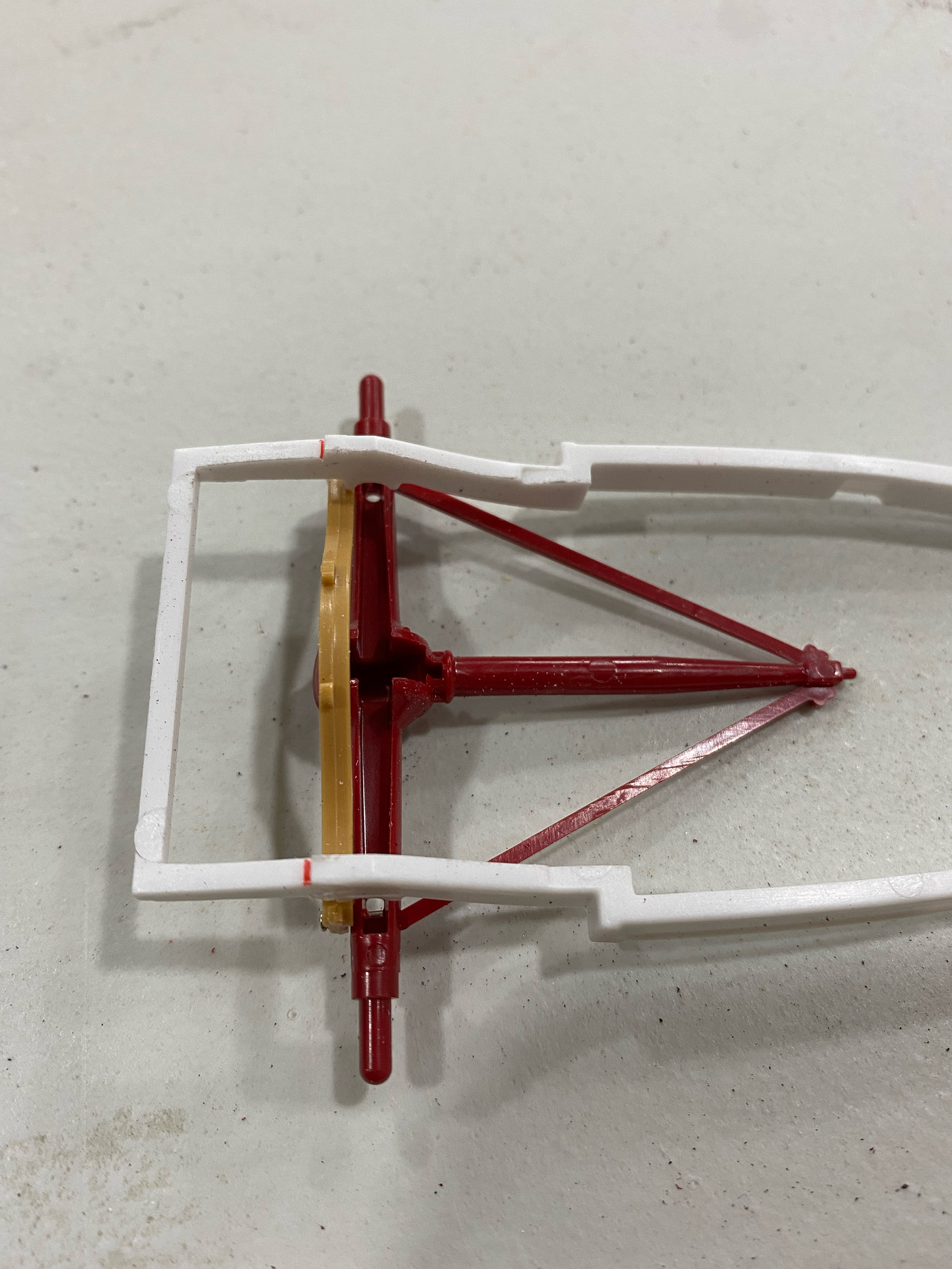 Then flip the frame over and lay it on top of the new crossmember. Center the crossmember on the frame side to side and make marks on the new crossmember on the inside of the frame (black marks). 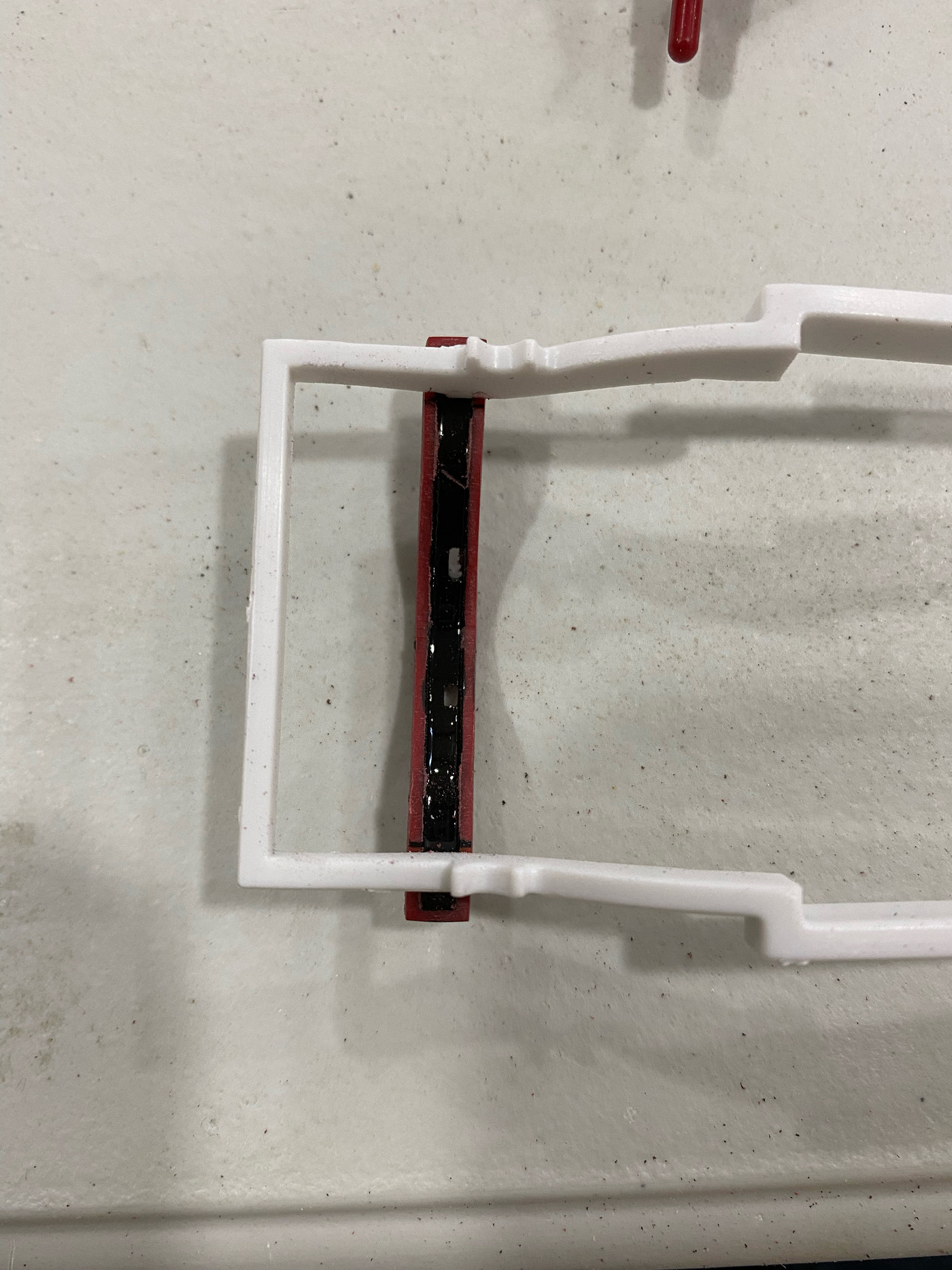 In this instance you will want to "leave the line". That means remove the flange material from the crossmember to allow it to sit flush on top of the frame, but only remove the material up to the line, leaving the line you marked so you get a nice tight fit. The pic illustrates the before on the left and after on the right. 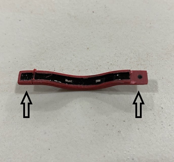 Set the fully modified crossmember on top of the frame and do any fine tuning to get the best interface between the parts. Once you're happy, glue the new crossmember to the frame. Once the glue has dried you can trim the excess material off the ends of the crossmember and sand/file it flush with the outside edge of the frame. Note the C notch in the frame to allow clearance for the spring on the upper frame rail 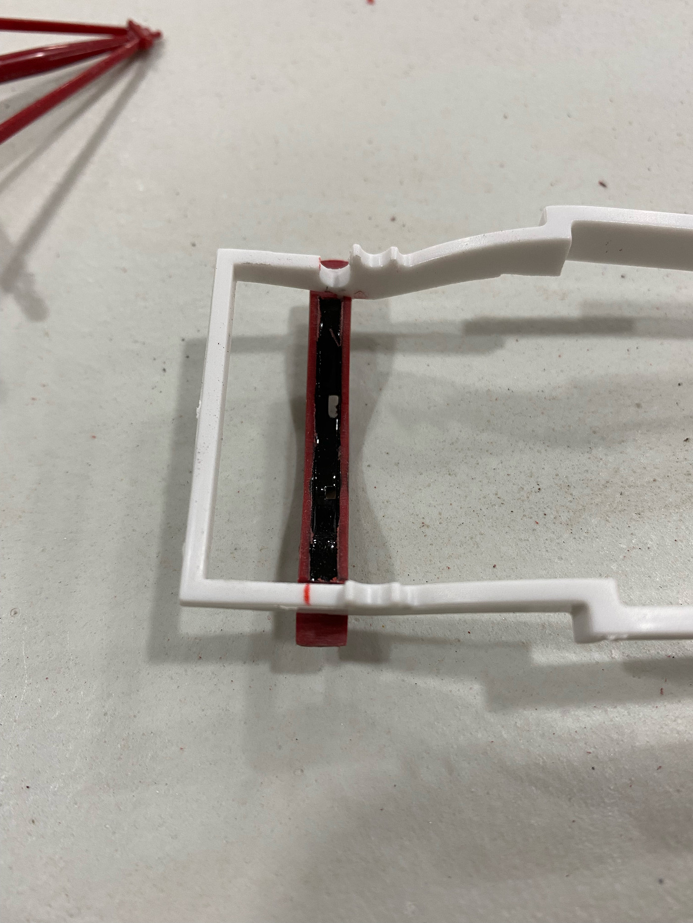 |
|
|
|
Post by chepp on Feb 14, 2022 10:41:10 GMT -5
That's a nice start. Thanks for the detailed how-to photos/instructions.
|
|
|
|
Post by Dave from Pleasanton on Feb 14, 2022 11:43:22 GMT -5
Craig, loving the build with the tips. I've bought several of the 29 Roadster and will do the same with the 30 coupe but haven't actually started one of them yet.
|
|
|
|
Post by hearsedriver on Feb 15, 2022 5:59:43 GMT -5
Great how to tips! Will be following this build with huge interest
|
|
|
|
Post by Mr. Metallic on Feb 15, 2022 10:47:46 GMT -5
Front suspension- Out of the box, the Revell Model A front axle puts the stance a bit high for my taste. Even if you spend time altering the front crossmember because the spring is mounted on top of the axle it will always sit high unless you Z the front end. Even though a Z is a pretty straightforward modification, there is a much simpler fix, and this one doesn't require any kitbashing. You can use what's right in the box. I've done this mod before, so I've got the steps down pretty well I think. Like I said in a previous post, I'm a big fan of pinning parts together, and here's another example. Take the kit axle/spring assembly and shave off the upper bolt head of the spring shackle (in the picture they would be exactly where the red marks are. Sorry I didn't get a before pic). After you shave off the bolt head take your drill and drill through the shackle, being sure to maintain the bit at a 90 degree angle to the part to ensure your hole goes straight through the back shackle. Once you have your hole, slide a pin through the hole and glue in place. The red ink makes the pin heads look huge, but they are much smaller in real life, especially when they aren't highlighted in red. 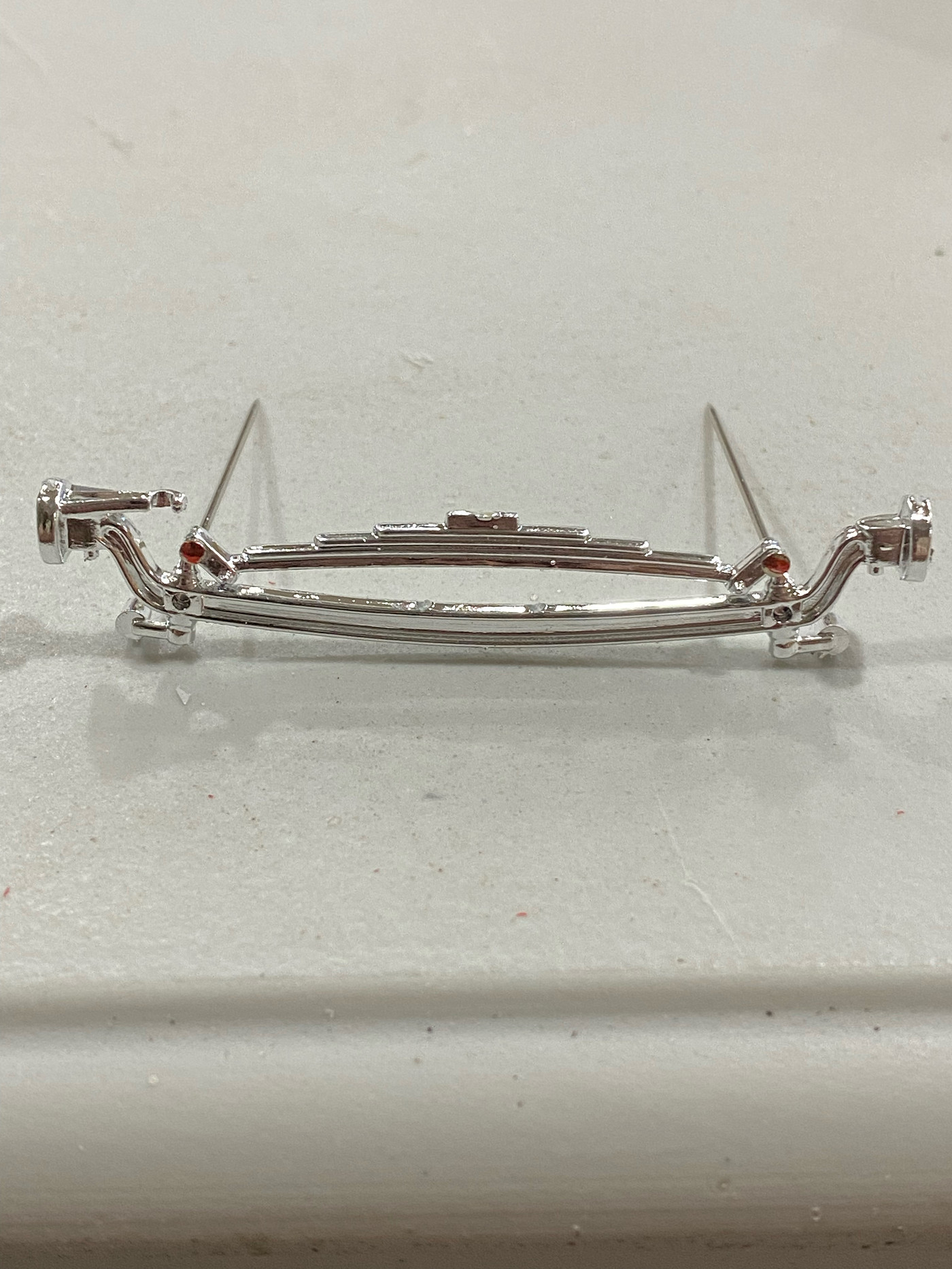 Once the glue dries you can then go ahead and sever the tiny connection point that ties the spring to the axle. If you drilled straight holes then your corresponding holes in the axle should land just inside the hole where the suspension arms will attach later. The pin holes are highlighted in red here. 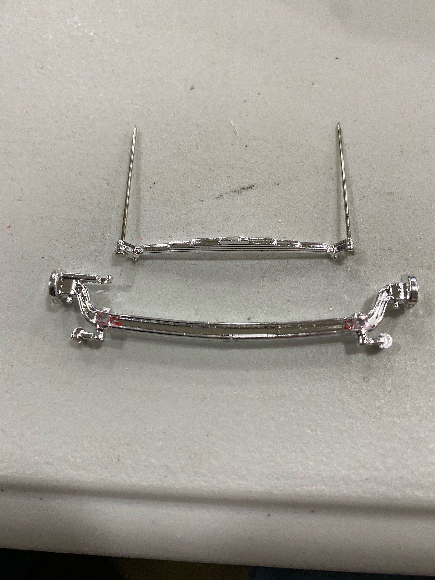 Now you are ready to mount the spring behind the axle by simply guiding your pins through the new holes in the axle. If you lined up your holes precisely everything should slide right together. If your holes are off slightly it's ok, just slightly open up the holes in the axle. The pins make your point stronger. At this point you can glue them together, but I will wait until I make my paint decisions. Here's before and after of the modification. 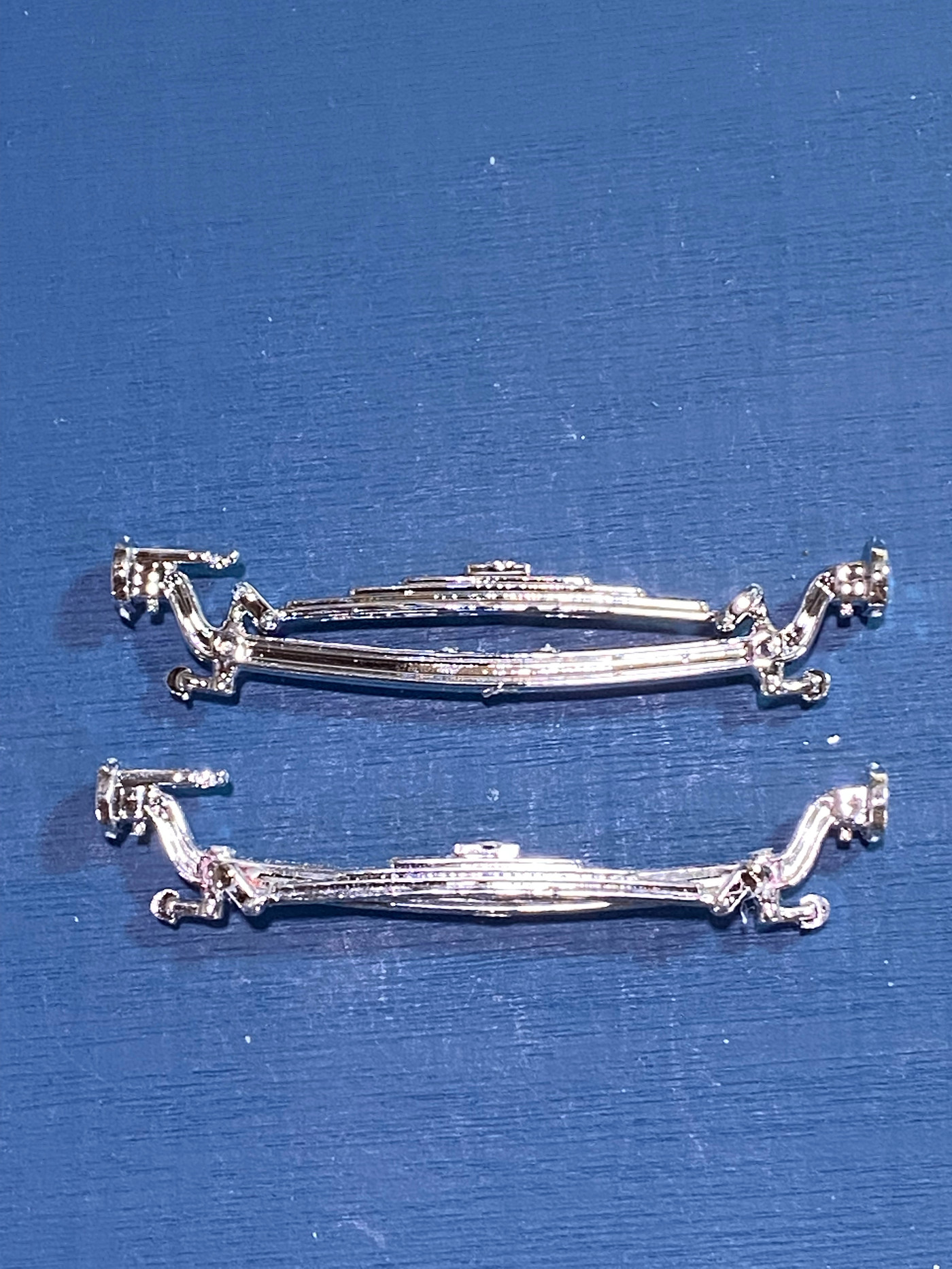 Now that you've successfully lowered the front end you will have to address the shock length. While doing this you can address another issue. Revell gives you a pretty solid assembly for the shock setup in this kit, incorporating the bracket for the shock and headlight mount all in one piece. However, this leaves the mounting bracket chrome, which is not typical in 1:1, so this is an opportunity to make the part more realistic while addressing the shock length issue. The kit piece is on the right, and you can see here where I snipped off the shock. Try to make your cut as close to the bracket as possible to retain as much of the shock length as you can in case you need the length later. Now drill a hole into the bracket to later receive the shock during final assembly. The angle of the hole is not critical, and really can be more of a dimple than a hole. You should then clean up the mold seams on the bracket and remove what's left of the chrome. Then glue the bracket to the corresponding notch in the frame. 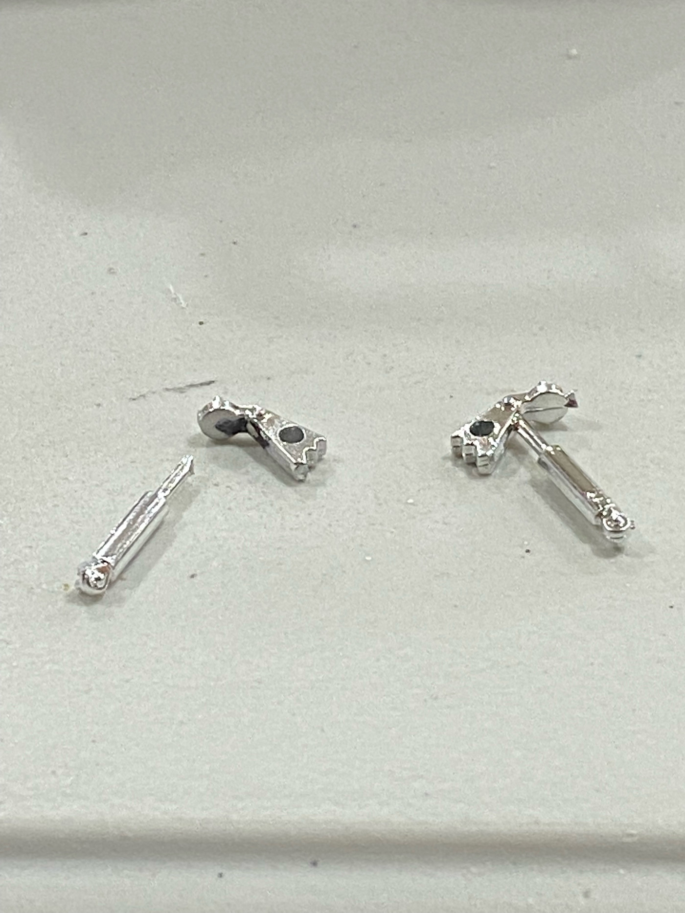 Down the road a little bit I'll make some alterations to the suspension arms, but for now you are ready to mock up your stance if you already have your wheel/tire choice figured out. I'll show how I created my wheel/tire combo in a later installment. This is where all your work starts to pay off. 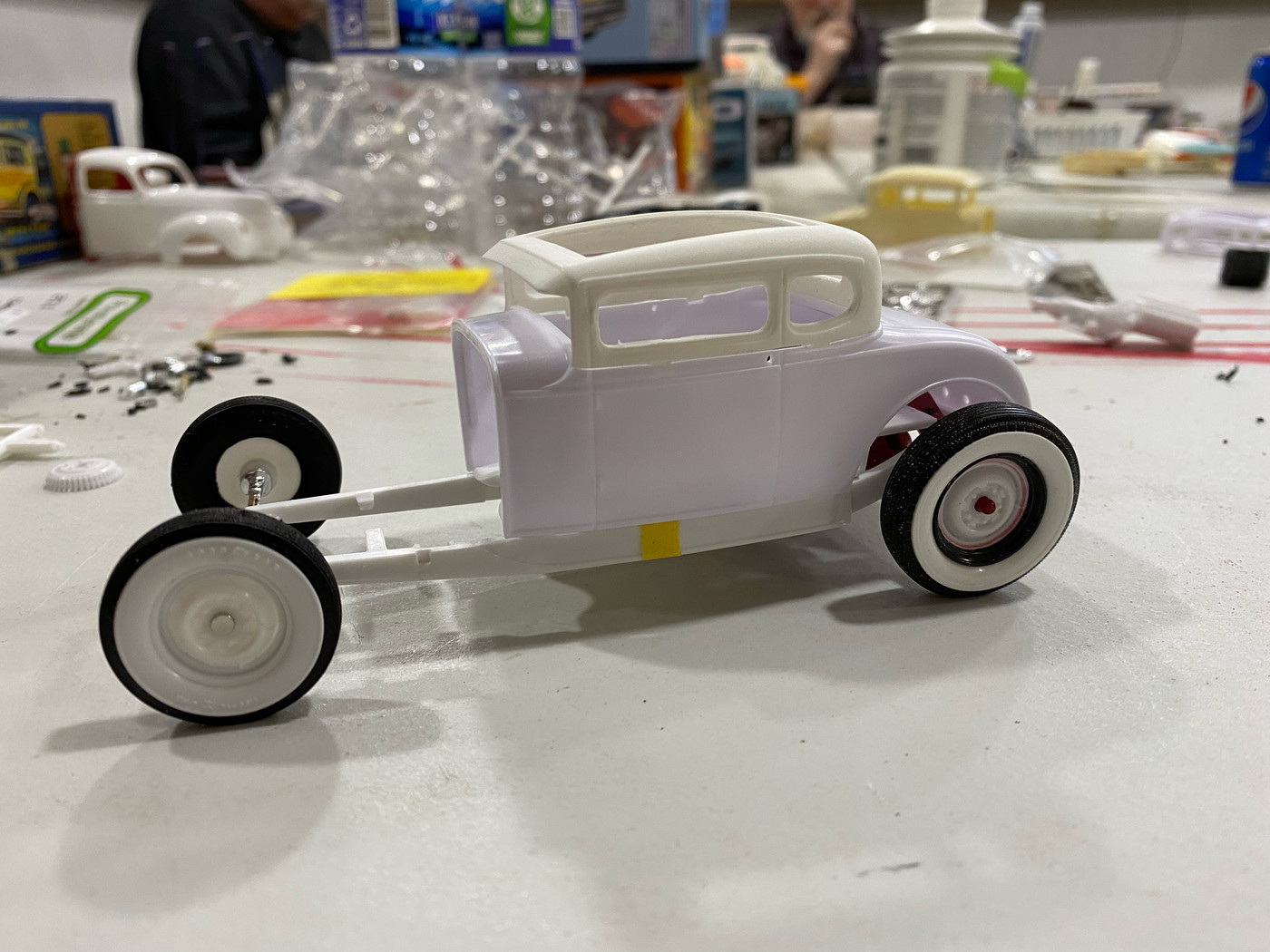 |
|
|
|
Post by Bernard Kron on Feb 15, 2022 16:40:13 GMT -5
Terrific series you've started here, Craig. I have a standard routine for prepping the Revell 1/25th Deuces (I use the same shock/shock mount prep you show here on that series) and this approach looks like the basis for another standard approach, addressing many of the issues that need changing on this more recent '29/'32 series from Revell. I especially like the approach you take to lowering the front axle. It's clean, precise and preserves much of the excellent detail of the kit parts, including the kit chrome. Looking forward to more!
|
|
|
|
Post by Mr. Metallic on Feb 16, 2022 8:36:22 GMT -5
Where the rubber meets the road- As most of you know there are three main items that impact the overall presence of a project sitting on the table in our segment of this hobby. Stance, wheels/tire combo and paint color. Since I already handled stance, lets move on to wheels/tires. Some may say that I'm doing this out of order because you need to know your wheels and tires before you can set your stance. That is true to a certain extent, except in this case I knew exactly what tires I was going to use, so I was able to set the stance accordingly. If you happen to follow my project as a template for your own hot rod and don't use the same wheels/tires you may end up having to adjust your stance a little, but that is just another part of building hot rods, both in scale and 1:1. The tires in the venerable Monogram 41 Lincoln kit make great traditional hot rod rear tires because they are just a bit taller than the standard sized tire offerings we get in most other kits, so this allows you to achieve a "rubber rake" by using standard size tires up front. There are other similarly tall tires out there, especially if you look at the classic car kits by MPC, AMT and Johan.(20's to 30's Cadillacs/Lincolns/Chryslers and Mercedes just to name a few). You may think to yourself, that Lincoln kit hasn't been around in a long time, where will I find one? Well they were reissued quite a few times over the last 50 years, and thankfully these wheels and tires were the same in all releases. And you can almost always find on old glue bomb or builtup at swap meets or eBay to steal the wheels/tires and engine from. Just get creative. Now, the tricky part about using the wheels from the Lincoln kit is they don't have any hub/lug nut detail. The center is meant to be covered by the beautiful Lincoln scripted hubcap, but that won't work for most hot rods. Therefor, you have to get a little creative. Over the years a few different methods have been shared to do this same process, but here's my take on it. This is what you start with, the Lincoln kit tire, wheel (molded in black) and the wheel from a Revell 40 Ford coupe. For those wondering, the front wheel and tire will be pulled directly from the Revell 40 Standard coupe, unmodified. 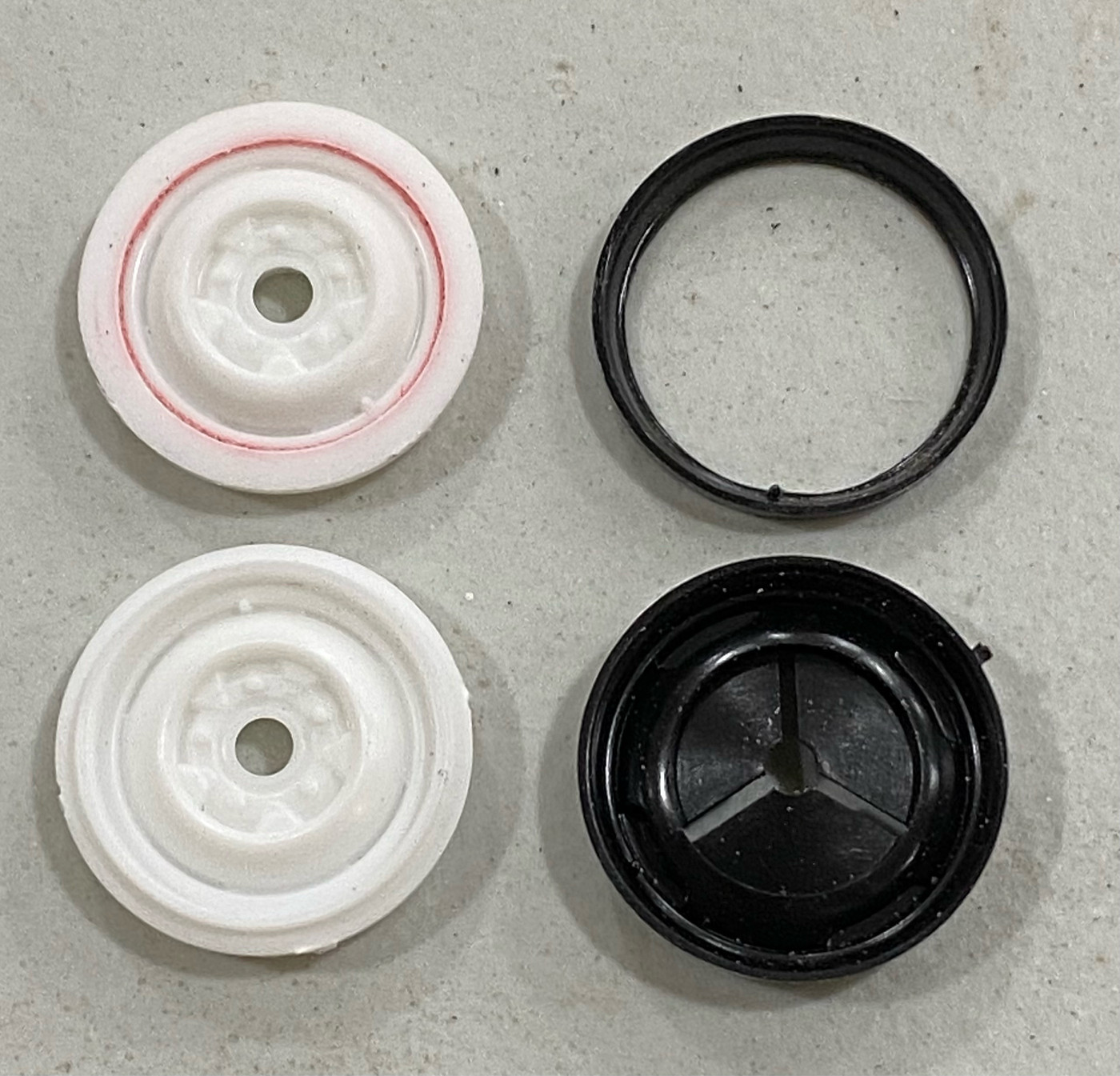 Start by grinding away all the material in that stepped down area that the red arrows are pointing toward. Take care to not intrude into that upper portion because that will form your wheel "hoop". Next take your 40 Ford wheel and using a fine tip marker mark (avoid a Sharpie or other permanent ink pen) and draw a line on the inside and outside of that wheel lip as pictured. This wheel lip would normally be the outer edge on a standard size wheel, but since we're going bigger you need a flat surface to attach the Lincoln wheel "hoop" to. Once marked, carefully remove the lip until it is flush with the outer edge. If you do your sanding correctly the line you drew on the outside will disappear, but the inner line will remain. In the pic below you can see the parts after they have been modified. Be sure to remove the little air nozzle (bottom the hoop in the pic) from the Lincoln wheel as the Ford wheel already has one molded in. 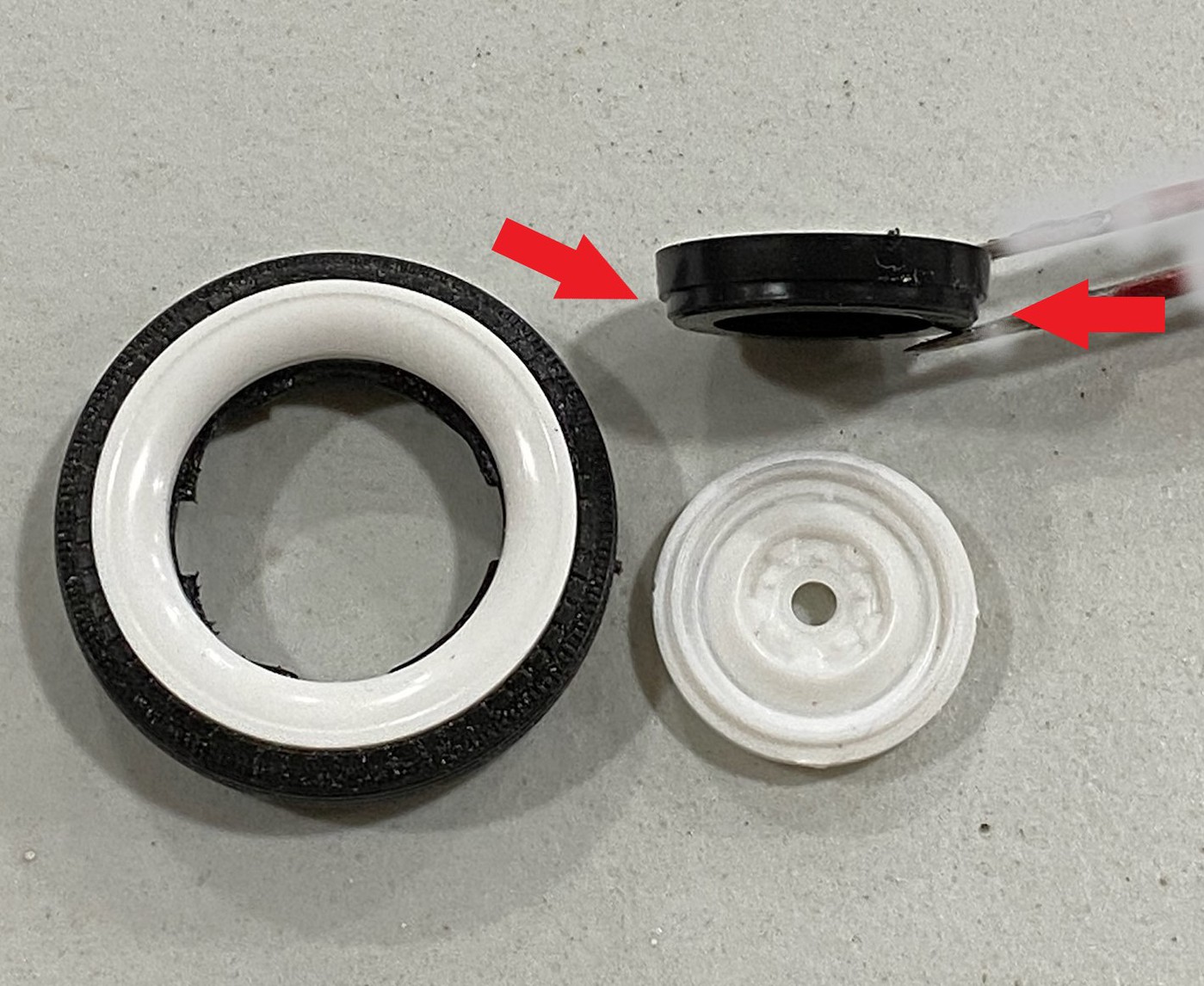 Now you should be ready to make your wheel. Check fitment of the two pieces together one more time to be sure you're happy, and then go ahead and glue them together, being sure to keep the Ford wheel centered in the Lincoln hoop. And now you can see that your work has paid off on the left, and the parts that got you there on the right. Scrub the wheels with soap and water before paint to remove your ink marks on the Ford wheel. 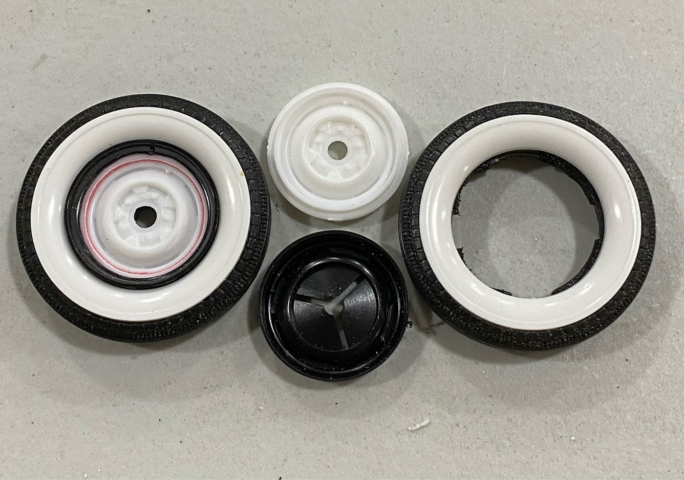 And lets modify the Lincoln wheel backs to work with the Revell Model A Buick brakes. On the left is the unmodified part. In the center is the piece highlighted where you will remove the center up to, and on the right is the finished piece. 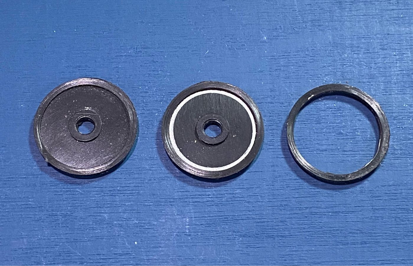 |
|
|
|
Post by Dave from Pleasanton on Feb 16, 2022 12:25:10 GMT -5
Craig, really enjoying the tips. It looks like you shortened the wheelbase, moving the spring ahead of the axle. I'm guessing that this is because of the radiator shell. Correct? Two things. You can remove permanent marker (Sharpie) with rubbing alcohol and I've never had a problem with the residue reacting to paint. I use nickel plated round head upholstery tacks as baby moons. I think the size is 3/8 (all my stuff is packed up because of my move). They need a little polish with Simichrome, but really look great. I think I got them at Hobby Lobby.
|
|
|
|
Post by Mr. Metallic on Feb 16, 2022 12:54:22 GMT -5
Craig, really enjoying the tips. It looks like you shortened the wheelbase, moving the spring ahead of the axle. I'm guessing that this is because of the radiator shell. Correct? Thanks for the tips Dave. And you caught me. Do as I say, not as I do  In the text I say to mount the spring behind the axle. That pic of the finished axle/spring assembly is actually from an old project, and when I took a pic I must have had the spring on the wrong side of the axle. I used the old pic because I realized I didn't snap a pic of the assembly for my current project when I was putting these posts together, so I dug up the old one. The spring should actually be mounted behind the axle, lengthening the wheelbase about 1-2 scale inches. Looks like I need to snap a new pic and update the thread for clarities sake. Thanks for the heads up. update- I took a new pic and have updated the thread. |
|
|
|
Post by Mr. Metallic on Feb 18, 2022 8:43:08 GMT -5
Armed and dangerous. (sorry, couldn't help myself) Now that we have the front and rear axles sorted out we need arms to locate them to the frame. Revell gives you two different sets of arms for the front axle, one for the channeled version, and one for the body-on-frame version. Select the set for the body-on-frame version and put the other set aside. To locate the front axle I'm using the kit supplied arms, slightly modified. The arm pictured at the top has had the head of the pivot bolt sanded off and is ready to have a hole for a pin drilled through it (marked in red). This area can get delicate, so take your time and make sure you keep the drill bit straight. After the hole is drilled all the way though you can carefully sever the mounting bracket from the arm. I use a photoetch saw blade for this because it is thinner than your standard razor saw. After the bracket is removed glue your pin in the hole on the arm. Once you're done with those mods you'll be left with the arm and bracket as pictured on the bottom here. You are now ready to glue the bracket into it's corresponding notch in the frame and the front suspension mods are essentially complete. 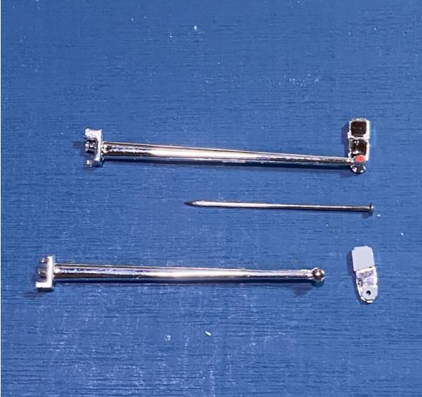 Now that the spring occupies the former mounting point for the suspension arms we need to drill a hole slightly outboard of the original point, highlighted here in red. 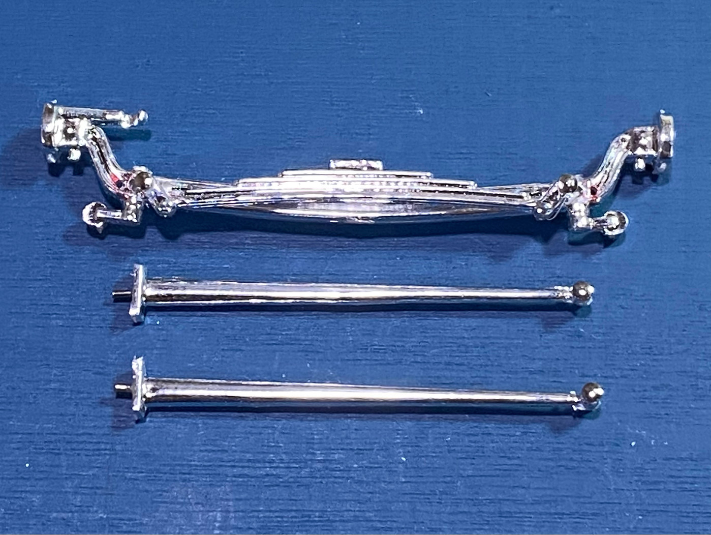 On to the rear! First off, that's not blood in the pic. We are going to use that second set of arms meant for the channeled version front axle and repurpose them for the rear. Here on the top arm in the picture I have removed one of the tiny tabs that are meant to locate the arm when you use it on the front axle, but because the rear axle is larger that tab gets in the way. In the second pic you can see I also went ahead and removed that plastic pin and replaced it with a metal one, and drilled a corresponding hole for it in the axle. The hole will be just inboard of that step on the outside of the axle where the brake backing plate will eventually rest. Go ahead and cut off the molded in "wishbone" arms from the axle at this time. 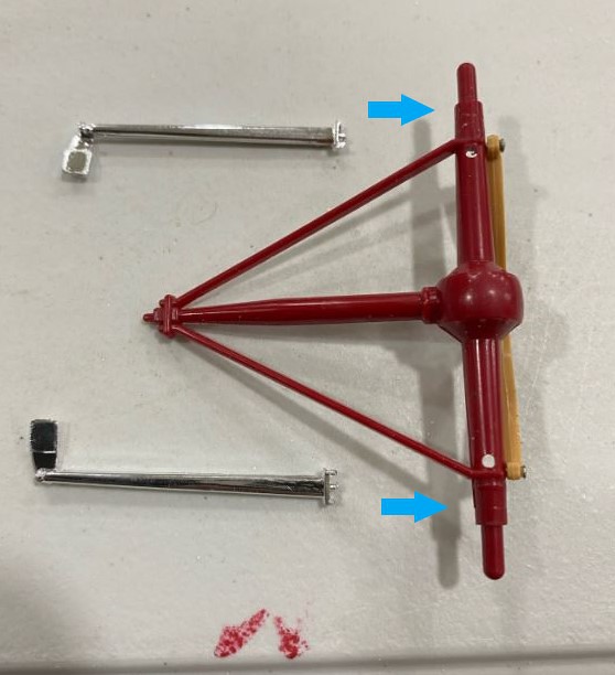 Here are the arms, I went ahead and performed the same pin procedure I did on the front arms, but instead of severing the bracket I removed it completely. 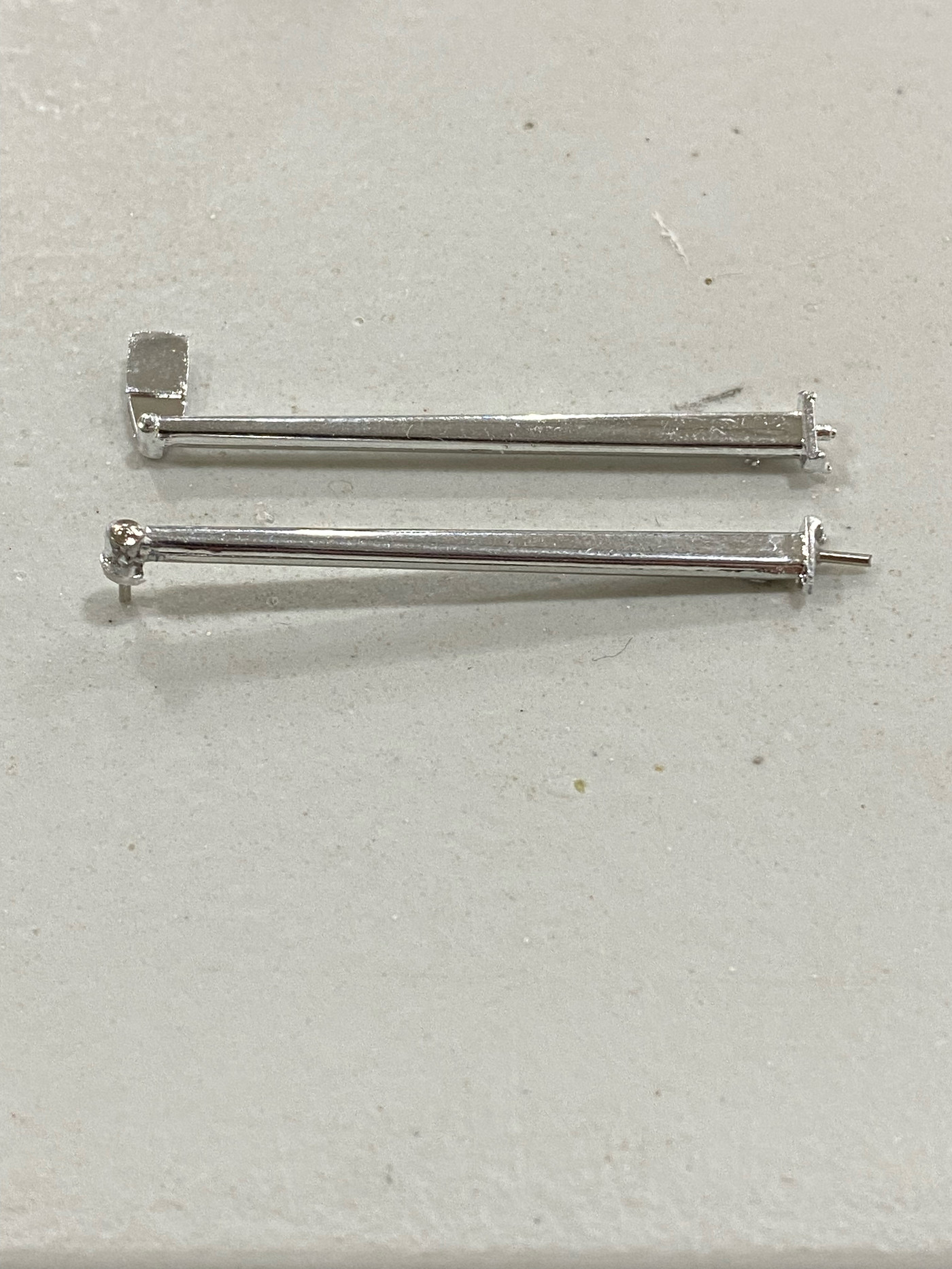 It's now time to mark and drill your pivot points. Place your spring/axle assembly in the crossmember on the frame. Take your arms and touch the pivot pin with a bit of ink, insert the pin on the other end into the axle, and then press the pivot pin against the frame, keeping the arm level with the axle and parallel to the bottom of the frame. The ink mark that is left tells you where to drill your hole to accept the pin. Drill your hole, and then mock up everything together like this. 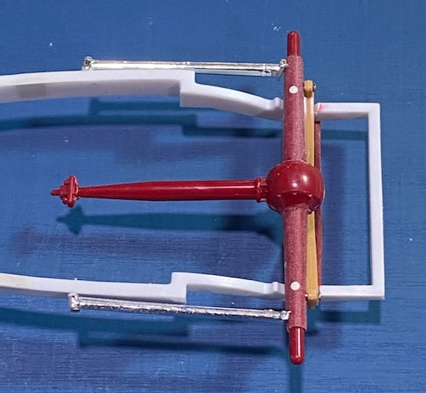 And here is the frame after the front arm brackets have been molded in and the rest of the frame smoothed out. Note the deletion of the notches for the kit supplied rear suspension arms. 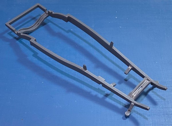 Now your suspensions are done. Normally I perform a mock up to check that I am happy with the stance and that everything fits together properly, but I forgot to snap a pic. I'll come back and add it in here later. |
|
|
|
Post by lo51merc on Feb 18, 2022 10:38:38 GMT -5
This is just so interesting to watch. And the precision of all those leetle holes, 👌 👏
Gary
|
|
|
|
Post by skip on Feb 19, 2022 2:04:25 GMT -5
Keep it up Craig, this one is looking good! I am watching with interest, I would say, "Baited-Breath" but that might reek too much, (depending on the bait)! Especially like your backdating methods on this frame and the parts you're using to do so. Lookin' Good!!
I have a Revell '29 Roadster pick up that I am thinking about putting on one of these chassis just to see what it will look like. In the planning stages so far. If it goes into production, it will run an Ardun OHV Flathead (eBay Glue Bomb Find, ick!), Quick Change Rear End on steel wheels. That's as far as I've got on that one yet.
|
|
|
|
Post by Mr. Metallic on Feb 21, 2022 7:54:12 GMT -5
And the moment we've all been waiting for...the mockup Yes, the body is shifted back on the frame and the rear axle is even further back. I was just so excited to see it mocked up I didn't pay attention to the details before I snapped the pic  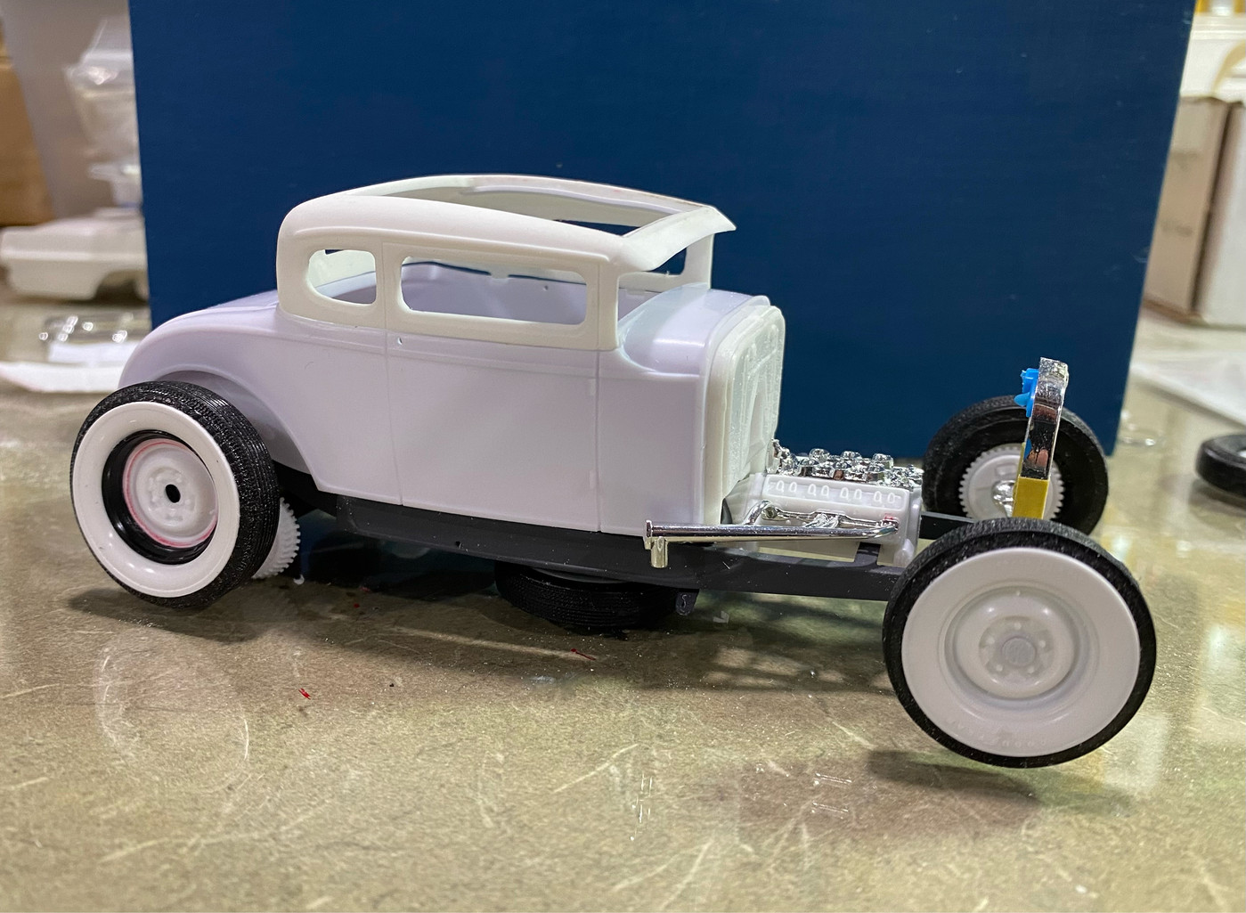 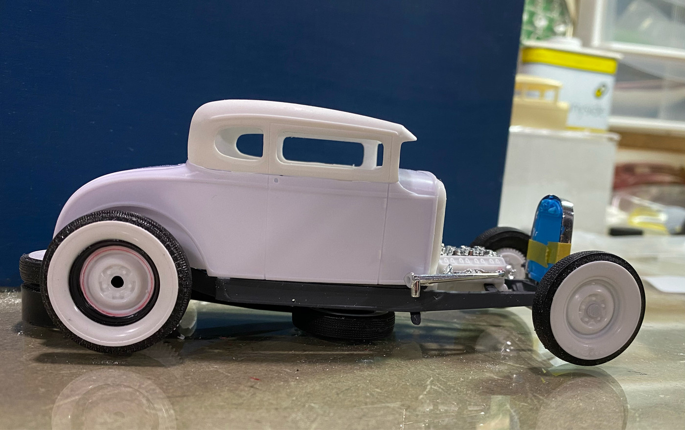 |
|
|
|
Post by Mr. Metallic on Feb 21, 2022 10:44:35 GMT -5
Interior- Not a ton of modifications happening here because Revell did a solid job with their interior straight out of the kit, just a few subtle things to help the overall appearance. There is always one thing that jumps out to me when I see these Revell Model A's built if it's not addressed. It's the notches in the sides of the interior where the side panels key into the floor. Those notches are highly visible from underneath. I started the process of addressing this earlier in the build buy making the floor pan sit flush on the frame. This helps hide those notches quite a bit, and you can stop there if you like, but I'm going a step further and just eliminating them altogether. First, select the size of plastic strip you will use to fill the gaps. It helps to select a size slightly larger than the notches themselves. Here is what you need, the floor, and 6 filler pieces. 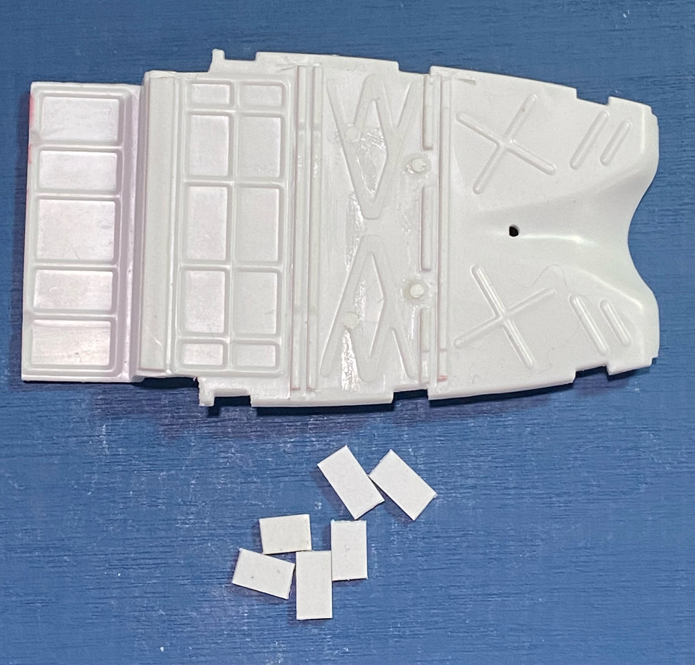 Enlarge the notches lightly to accept the strips. Cut the strips a little long to give you something to hold on to and allow for precise trimming later. Glue your fillers into the notches and let the glue cure. I also took this opportunity to fill the round holes for the crossmember. You may also note that I cut off the tail end of the floor pan to accommodate the new spring crossmember. This will be covered in a later installment. 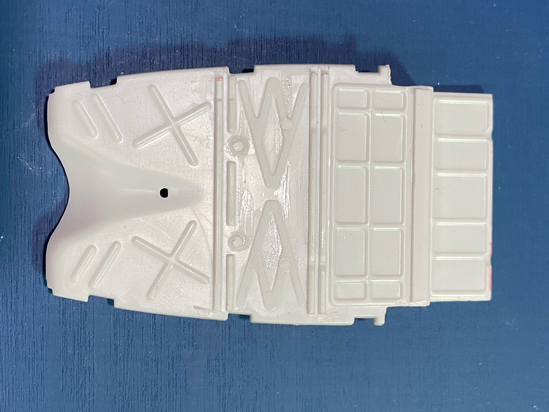 Trim the filler pieces flush with the floor, and then treat the areas with a little filler to blend them in. Then you're ready to prime. The extra holes in the rear axle have also been filled, and the mods to the K-member from a Revell 32 Ford kit have been completed. 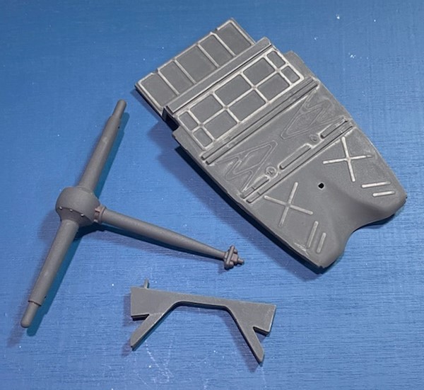 Now we can address the side panels. Revell made the interesting choice to mold the rear inner fenderwells in conjunction with the interior side panels. They are meant to be a part of the body, so lets make things easier on ourselves and just remove them and attach them to the body. Draw a straight line from the upper rear corner of the pleated interior down to just in front of the fenderwell. Sever the fenderwell insert and glue it to the body. We are going to fill this notch that ends up below the rear windows (arrows), so square up that opening to accept the styrene strip of your choice. You will want to pick a strip that will be flush or taller than the rest of the top of the panel so you can sand it flush. Also clip off the the tabs at the bottom marked with red X's.  Here is why we are filling that notch below the back windows. It was probably made to allow space for the clear piece to fit there, but I'll be replacing these windows with acetate, so I don't need the room and this will look better. If you're going to use the kit glass here, omit this mod. 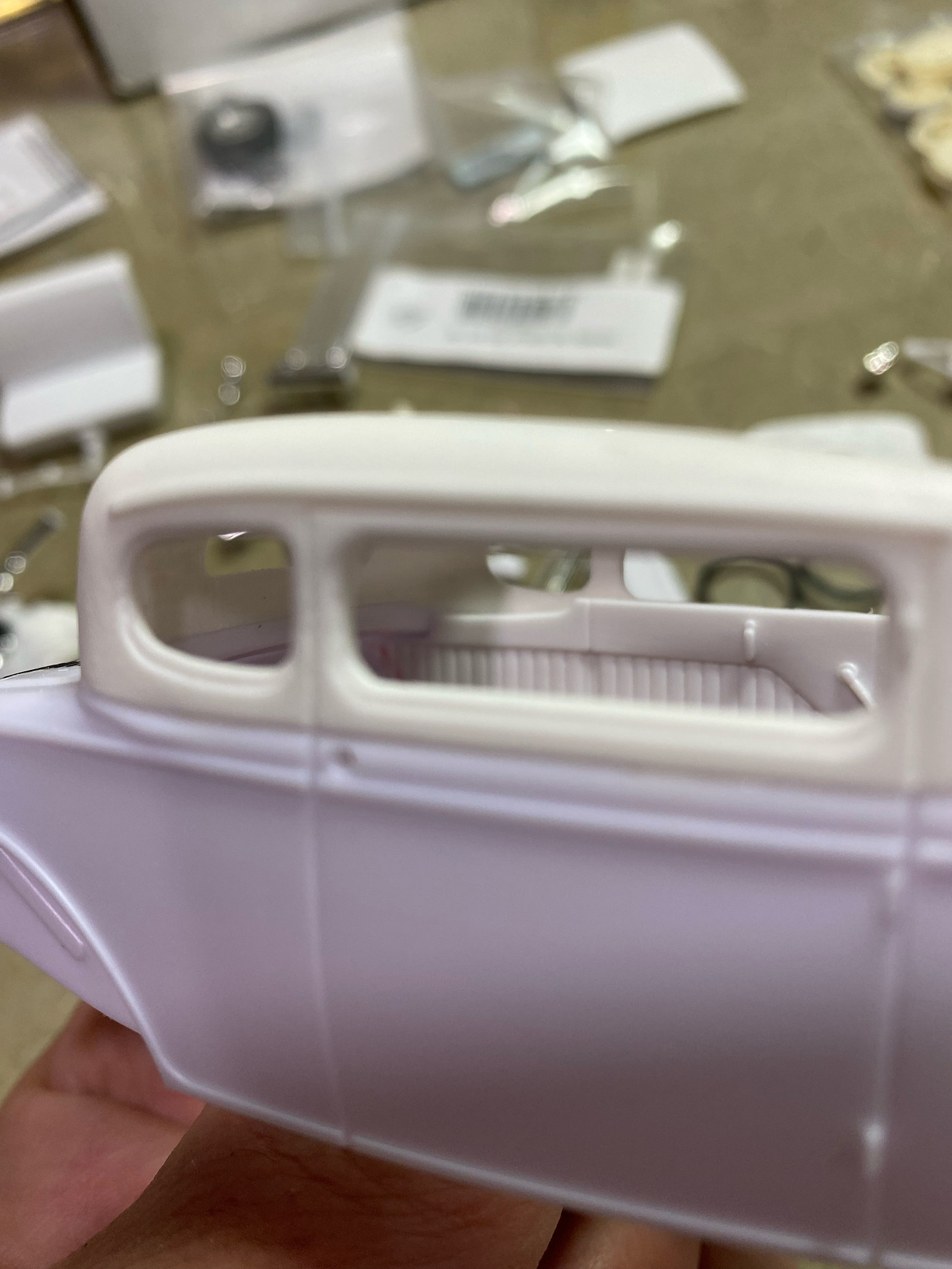 The top panel in the pic has bit hit with a little filler to the notch, and now has been fully modified and is ready for primer/paint. This is the extent I'll be going with modifications to the interior on this project, but the canvas Revell has provided is great for personalization, including seat swaps and adding detail. 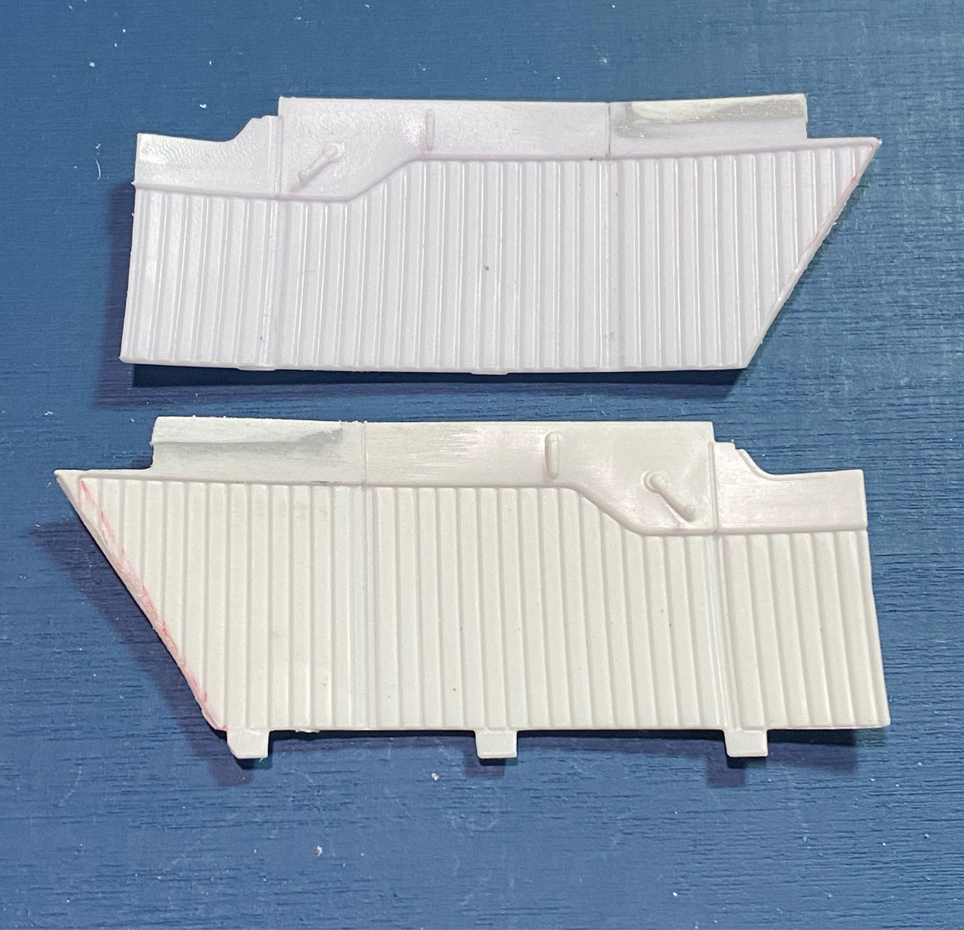 |
|


 In the text I say to mount the spring behind the axle. That pic of the finished axle/spring assembly is actually from an old project, and when I took a pic I must have had the spring on the wrong side of the axle. I used the old pic because I realized I didn't snap a pic of the assembly for my current project when I was putting these posts together, so I dug up the old one. The spring should actually be mounted behind the axle, lengthening the wheelbase about 1-2 scale inches. Looks like I need to snap a new pic and update the thread for clarities sake. Thanks for the heads up.


